If you missed part 2 please find it here.
Finishing the frame and mounting the gears
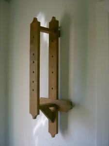
The frame is finished with spacers on the backside and holes for the axles. The spacers on the backside are designed to create a space for the pendulum between the frame and the wall.


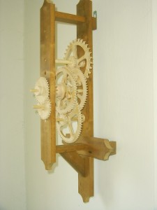
In the last photo all the gears are mounted in the frame as a test to see if they will actually work together. I assembled the rest (pendulum and all) and started testing how much weight it takes to run the clock. Brian Law suggests starting with 6 pounds but I chose to start considerably lower with 1 kilo.
Here my first serious setback happened in the project. There is a piece in the shape of a semicircle (number 31 in the plans) that allows the clock to be winded and prevents the spool holding the weight from running backwards. It broke and the weight fell on the floor with a bang! It was simply to tiny to hold the weight.
After a few “blessings” I started all over again with a new spool (number 34 on the plans) and two new gears (numbers 30 and 36 on the plans). I chose to make the spool diameter larger (about 1.5 times the original) and to create a gear with larger teeth than the original (number 36 in the plans). Of course I had to create a new version of number 31 on the plans that will fit my new gear (number 36) and be stronger than the original.
I then reassembled the clock for another test and it actually works. 🙂