If you missed part 3, please find it here.
Splitting g-code
So far we have created a drawing in OpenSCAD and generated 4 g-code files in FreeMILL: two files with a flat tool and a step distance of 2,8 mm (one in each direction) and two files with a ball nose tool and a step distance of 0,4 mm (one in each direction).
The two files created for at ball nose tool and a step distance of 0,4 mm are going to be used for the last two runs to finish the surface and to make it nice and smooth. The other two files are going to the split into several smaller files that will allow the CNC machine to work its way down into the material one millimeter at a time.
For that purpose I created a small program (with some valuable input from my friend Mads) which will do just that. It’s called G-Code Utility and can be downloaded here. Use it at your own risk! It comes with no warranty so please test the generated g-code before using it – for your own safety! G-Code Utility is built for this purpose only: Splitting g-code generated in FreeMILL as described in my earlier post! Remember: Carefulness is essential when working with high powered, fast spinning sharp tools like a CNC machine. I cannot stress that enough…
G-Code Utility
Since the g-code generated by FreeMILL describes the surface of our Dominion turntable and the ShapeOko 2 isn’t capable of milling the deepest holes (the deepest hole is 18 mm deep compared to the surface of the stock) in one run, we have to do something.
What G-Code Utility does is this: Finds the deepest place on the surface (here it is -18 mm), adds one millimeter (can be changed) and generates a file with the g-code that will cut anything below that limit (in this case -17 mm). Adds another millimeter to the limit and generates a new file with the g-code that will cut anything below this new limit (in this case -16mm) and so on.
Furthermore, it adds the current limit to the z-values in the file so we can run all of them from the same zero and it will try to choose the next path to be the one closest to the current machine position. This may sometimes generate an odd choice for the next path since it’s a mathematical calculated value – and not the logical choice for a human!
Splitting the g-code in the x-direction
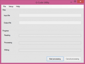
When you start G-Code Utility it looks like this:
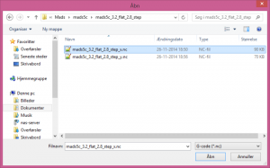
Go to File -> Input file and select the g-code file generated by FreeMILL and press “Open”. Remember, we are using the file we generated for a flat tool 3,2 mm i diameter and with a step distance of 2,8 mm. In my case it’s called “mads5c_3.2_flat_2.8_step_x.nc” as seen in the screen dump.
Now, got to File -> Output file and type in the name that you want to prefix your output files and press “Save”. In my case I choose “mads5c_3.2_flat_2.8_step_x_mod.nc” (“mod” for “modified”).
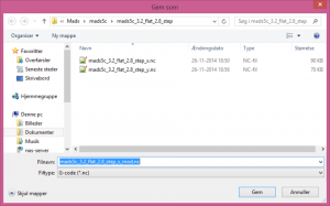
G-Code Utility will then generate files with file names on the form “mads5c_3.2_flat_2.8_step_x_mod(limit -X.XX).nc” where X.XX is the limit used in that particular file.
Go to Setup -> Options to display the options:
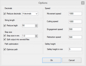
The default options displayed above are the option I use for my ShapeOko 2. They should be quite easy to understand but here’s the explanation anyway:
Decimals -> Reduce decimals
Check to reduce decimals in the code. There is no reason to use more than 4 decimals when sending coordinates to the g-shield.
String length -> Reduce length
Check to reduce string length. The g-shield can only take strings of length 50 characters. You can change it if you use another shield.
Step size -> Step size in mm.
Change to change the difference in depth used in the files generated by G-Code Utility. Never use a value larger than half the diameter of the tool you’re going to use.
Step size -> Split output into several files
If unchecked G-Code Utility will only generate one output file with the g-code for each step collected in section so the CNC machine will first run g-code for maximum depth plus limit, then code for maximum depth plus 2 time the limit, and so on.
Path optimization -> Optimize path
If unchecked G-Code Utility will not try to take the closest path as the next one. Instead it will simply take the next path in the original file.
Speed -> Movement speed
The movement speed (when not cutting) in mm per minute.
Speed -> Cutting speed
The speed in mm per minute when cutting.
Speed -> Engagement speed
The speed in mm per minute used when moving the cutter into the stock (downwards). Should in my experience never be more than 1000 mm/minute. Values higher than 1000 can cause the z-axis stepper motor to skip some steps.
Speed -> Retraction speed
The speed in mm per minute used when moving the cutter out of the stock (upwards). Should in my experience never be more than 1000 mm/minute. Values higher than 1000 can cause the z-axis stepper motor to skip some steps.
Safety height -> Safety height in mm
Determines the distance above the stock where the CNC machine can safely move without cutting. Should never be less than 1.
Processing
When you’re satisfied with your choices, press “Start processing” in the main window. It will process the file in the background and tell you the result in a dialog. The three progress bars will tell you how your job is progressing.
Thats it! We’ve now split the original file into several files with limits from -17 mm to -1 mm. Now we just need to repeat the process with the file for the y-direction.
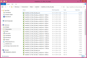
Control the g-code files generated by G-Code Utility
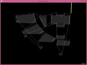
I always check the generated g-code files with a g-code viewer (there are several versions available – even on-line versions) just to see if it looks reasonable to me. In this case I’ve shown the file “mads5c_3.2_flat_2.8_step_x_mod(limit -7.00).nc” viewed in Universal Gcode Sender in file mode.
When you feel comfortable with the g-code you’ve generated it’s time to go to the workshop! 🙂