My grbl shield is broken
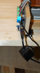
When I first built my ShapeOko 2, I placed the Arduino and the grbl shield at the out most corner of the frame. This has proven to be a mistake in several ways… 🙁

First of all, it gets all the dust from the machine so it has to be cleaned regularly using a vacuum cleaner or compressed air. This is a bad idea…
Second, the wires going to the stepper motors are so heavy the they have a tendency to put pressure on the terminals, when the machine is running. Not good either…
So, the result was that the out most potentiometer (white square thing in the photo just below the power terminal) broke loose and caused me all sorts of problem. Since it’s part of the control of the z-axis, I experienced all sorts of troubles with the stepper motor running the z-axis. For instance it would work perfectly for an hour but suddenly stop moving the z-axis at all or (even worse) skip a few millimeters and then continue as if nothing had happened… 😮
I took me a while to locate the cause of the problem (after all sorts of testing) and a fix turned out to be a challenge, too.
A new shield
First of all I decided to buy a replacement shield, but since ordering things from the USA can be a rather expensive experience due to danish duties, fees and shipment costs, I decided to go for an alternative shield. I’ve ordered a gaups shield from ASL (Amber Spyglass Ltd.) which is located in the UK. This means that they are within the EU and therefore goods sent from them aren’t subject to danish duties. But there is also a backside to that approach: ASL is run as a spare time project and thus shipping time can be quite long, since the owner has a full time job on top of running the shop. I guess I’ll just have to be patient and wait for the package to arrive.
In the meantime
A broken grbl shield and a ongoing project on the ShapeOko for a friend isn’t the best of combinations, so what to do?
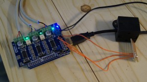
A first I considered soldering the potentiometer back on but since it’s located just below the power terminal, it turned out to be impossible for me to find enough space for soldering it directly on the PCB. But as a matter of fact, I managed to remove it from the PCB and solder three wires in place where the connectors of the potentiometer used to be. This enabled me to make a temporarily solution by soldering the potentiometer onto a small piece of PCB and then connect the wires there. It’s not pretty but it allows me to continue my project. 🙂

A better solution
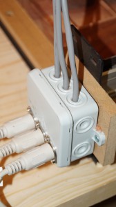
Since I had the electronics taken apart for repair, I decided not to put it back on the frame of the ShappeOko. Instead I placed a plastic box with three DIN sockets connected to the wires going to the stepper motors and then use some cables with DIN connectors I had in store to connect the grbl shield to the machine. I think it’s a better solution, once I get around to building a cabinet for the electronics. It currently looks like this:

Hopefully, I end up with the electronics placed in some distance from the machine (out of harms way). 🙂
Once I receive the parts from ASL, I’ll get back to this subject…